How to prepare a complete specification for a solenoid coil
The basis for the successful production of solenoid coils is a CAD drawing as well as a proper layout of the most important parameters. In order to make rapid progress in product development, it is important that the essential requirements for a customer-specific coil are specified.
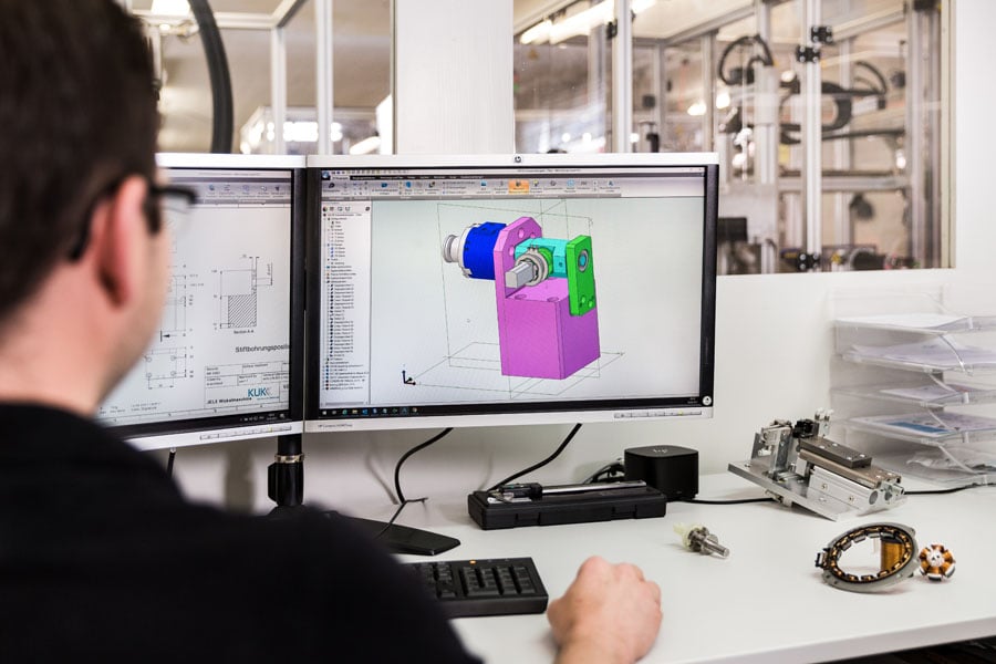
This article provides an overview of the most common parameters required for the production of solenoid coils. Depending on the type of coil intended, additional data may be necessary to complete the design.
Wire diameter (in mm)
Diameter of the pure copper (or alternative conductor material) of the coil wire, without insulation layer. Relevant for weight and resistance.
Wire outer diameter (in mm)
Effective outer diameter of the wire with conductor material (copper or alternative conductor material) plus insulation (enamel). At least the adequate degree of insulation is required.
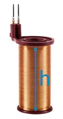
Coil height (in mm)
Height h from the beginning to the end of the windings. Sometimes also referred to as coil length, but this is confusing, especially with rectangular coils.
Inner contour
Either:- Inner diameter (in mm) for cylindrical coil or
- Length and width (in mm) for square coil incl. corner radii
Windings/turns
Desired number of turns to be wound on the solenoid coil. Influences, among other things, the outside diameter of the coil and the resistance. Alternatively, the maximum number of turns possible in the installation space or the number of turns required to achieve resistance R can be specified here. 
Optional parameters for coil production
The following values result from the parameters mentioned above, they are therefore optional. However, depending on the application, they may have a priority importance for the coil production. In such cases it is vital that this is indicated by the developer.
Resistance (in Ω)
Expected resistance of the coil. If the number of turns is not known, but the resistance is relevant, the resistance can be indicated instead of the number of turns. Please note: depending on the coil +/- 5-10 % tolerance.
Outside diameter of the coil (in mm)
Expected outside diameter with tolerance.
Layers
Number of layers in which windings are wound on top of each other. Is given by the number of turns and the height of the bobbin.
Windings per layer
Number of turns per layer. Is given by wire diameter and coil height.
Inductance (in mH)
The inductance of a coil is given by the number of turns, inner contour and coil height, among other things.
Co-engineering with leading manufacturer of coils and electronics
Given the limited space available for a solenoid coil, or other constraints, there are often trade-offs between individual values. As an engineer, you know which parameters have priority for your application. A customer-specific coil manufacturer such as KUK Group can advise you during the development phase of the possibilities that exist in the manufacturing process. A CAD drawing as well as a proper design along the values described here are an optimal basis to do so.

